
First, let's see why do impedance matching?
Impedance matching can not be done in low-speed PCB design, but in high-speed PCB design to obtain a complete, reliable, accurate, non-interference, noise transmission signal. It is necessary to ensure that the circuit performance provided by the printed circuit board ensures that the signal does not reflect during the transmission process, the signal is complete, the transmission loss is low, and the function of matching the impedance is played. If the key signal does not reach the impedance match, it may lead to the reflection and rebound loss of the signal, and the original good signal waveform will be deformed. This will directly affect the performance and even the function of our circuit.
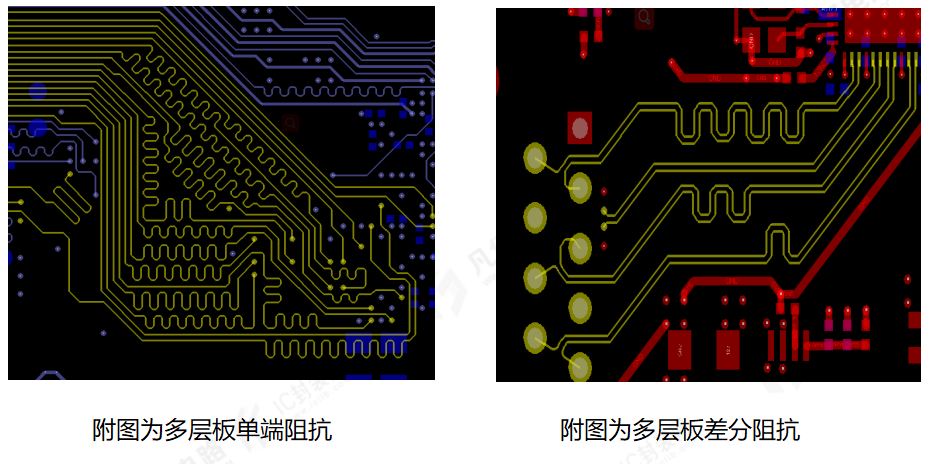
Second, what types of impedance lines are there?
Generally, our impedance lines can be divided into single-ended impedance and differential impedance. In the multi-layer board, the single-ended line and the differential line refer to adjacent layers. It should be noted that the interlayer reference will be carried out in the processing of RF lines to ensure the optimal line width of the RF antenna so as to achieve the best performance. The so-called coplanar impedance means that the single terminal line or differential line that needs to do impedance matching usually refers to the copper sheet on both sides of the signal line to achieve an impedance matching purpose.
Third, what lines usually need to control the impedance, how much European impedance need to be controlled?
Not all lines have impedance matching requirements, high-speed lines need to control impedance, different signal impedance values are not the same, differential impedance 90om, 100om, 120om, etc., general USB2.0 requires control 90om impedance, HDMI,USB3.0,MIPI, 100 Mbit/s network port, gigabit network port, etc., is to control 100om impedance, RS422 is generally controlled by 120om impedance. Single terminal line can generally control 50om impedance.
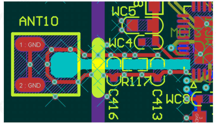
Fourth, after the completion of the PCB design, how to butt with the board factory to make it understand which lines need to do impedance matching?
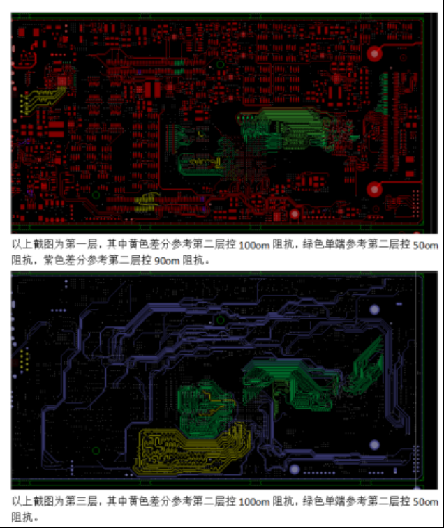
After we complete the PCB design, we usually explain the impedance matching of our board to the board factory in the way of screenshot description, as shown in the following figure, the signal line with different impedance values is marked with a color to distinguish, and then the screenshot with text description can be!