
With the rapid development of technology, the size of modern electronic components is shrinking day by day. The pin pitch of fine-pitch integrated circuits has been reduced from 0.5 millimeters to 0.3 millimeters, which poses a considerable challenge to the SMT process.

Precisely soldering these tiny components on the circuit board to avoid defects such as empty soldering, continuous soldering and standing stones is a severe test. The greater challenge lies in the fact that there are both large and small components on the same circuit board, and their requirements for the amount of solder are completely different. Generally, large components require more solder to ensure a stable soldering, while small components need to precisely control the amount of solder paste. A slight mistake may lead to soldering defects.
To solve this difficult problem, the step steel mesh technology emerged. The following picture shows local thickening. The thickening is on one side of the scraper. Similarly, you can also locally thin it.

This technology precisely controls the amount of solder paste by differentiating the thickness of solder paste in different areas on the same steel mesh. Step steel mesh is divided into two types: upper steel mesh (partially thickened) and lower steel mesh (partially thinned). The upper steel mesh, by increasing the amount of solder paste in specific areas, is suitable for parts such as USB interfaces or large connectors, and at the same time helps to improve the problem of coplanarity of pins. The lower steel mesh prevents short-circuiting of fine-pitch components due to excessive solder paste by reducing the amount of solder paste.
When using step steel mesh, several points should be noted:
The thickened steel mesh area is usually placed on the other side of the scraper to reduce the risk of damage to the scraper. Of course, this is not absolute. You can also place a locally thickened one on one side of the scraper, but it may affect the lifespan of the scraper.
In addition, the price of this type of special steel mesh is about 10% higher than that of ordinary steel mesh because of its complex manufacturing process, which requires the use of thicker steel sheets and laser cutting. Although increasing the thickness of the steel mesh can increase the amount of solder paste, it is still necessary to pay attention to the small components around to avoid problems caused by the increase in solder content.
It is generally recommended that the thickness difference of the same steel mesh be controlled within 0.03 millimeters. The stepped steel mesh technology also puts forward new requirements for the design layout of circuit boards. Reasonable placement of components requiring different tin amounts and avoiding sudden thickness changes on the same scraper path are the keys to optimizing the soldering effect.
Overall, through meticulous design and manufacturing processes, step steel mesh provides a flexible and reliable solution for modern electronic assembly, ensuring the soldering quality and long-term stability of complex circuit boards.
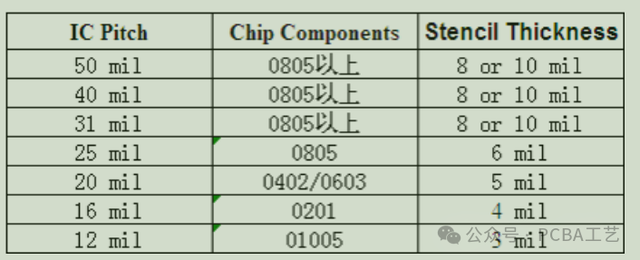
Based on experience, generally speaking, if there are fine-pitch parts or similar devices like 0201 on the board, and considering other parts, the overall thickness of the steel mesh should be controlled at 6mil, and the fine-pitch parts or 0201 devices need to be controlled at 4mil, then you can confidently make the step steel mesh. Of course, there are some individual components that may require more solder paste, such as connectors and transformers.
If the overall thickness of your steel mesh is 5mil, you can add 7mil to some parts. Actually, it's not as profound and difficult to understand as you might think. However, it's important to note that the periphery of the steps is generally around 3 to 5mm, and it's best not to have any other components. Especially for fine-pitch or 0201 devices, otherwise it may affect the solder paste thickness of the surrounding devices. The following figure shows the general selection of steel mesh thickness corresponding to chip materials and fine-pitch devices, which can serve as a reference for you.