
Precautions for PCB design and assembly of display screens
The core of the assembly of the display screen PCBA (including core boards such as drivers, power supplies, and timing control) is to ensure electrical safety, signal stability, and long-term durability. It is necessary to focus on the three core aspects of "high-voltage isolation, high-frequency anti-interference, and adaptive protection", and pay special attention to five key matters:
first. Electrical Safety: Eliminate High-voltage Risks (Power Supply/Drive Board Core)
• Strict separation of high and low voltage: Clearly define the "high-voltage zone" (AC input, power rectifier circuit) and the "low-voltage zone" (driver IC, signal line), with a distance of no less than 8mm. Add a creepage isolation slot or attach an insulating Mylar sheet in the middle to prevent breakdown and short circuit.
• Safety components cannot be replaced: The fuses, X/Y capacitors, and varistors on the power board must be safety components with UL/VDE certification. The pins of the high-voltage capacitor are reserved with an explosion-proof gap of ≥3mm to prevent explosion at high temperatures.
• Soldering and wiring specifications: High-voltage solder joints must be "fully soldered" (solder covering the pad ≥80%), and false soldering is strictly prohibited. When wiring the AC terminal, strip the wire by 3-5mm (with no copper wire exposed), and the terminal tightening torque should be ≥0.8N·m to prevent loosening and sparking.
second. Signal Stability: Ensure no abnormal display (Timing/Driver board Focus)
• Layout anti-interference design:
1. The distance between high-frequency signal lines (LVDS screen lines, clock signals) and high-current lines (backlight driver lines) should be no less than 5mm to avoid crosstalk causing screen flickering or screen flickering.
2. A "ground ring" (large-area copper-clad grounding) is made around the timing chip (T-Con IC) to absorb high-frequency noise. The clock line is short and straight (≤10cm), with 50Ω matching resistors added at both ends to prevent signal reflection.
• Precise connector fitting: The LVDS screen cable and screen body ribbon cable interfaces need to be "correctly inserted" and the clips should be securely fastened. If necessary, apply a small amount of hot melt adhesive at the interface for fixation. Do not pull the wire when it is in the plug-in state to prevent the pins from bending.
Third. Components and Mounting: Adapt to the characteristics of display screens
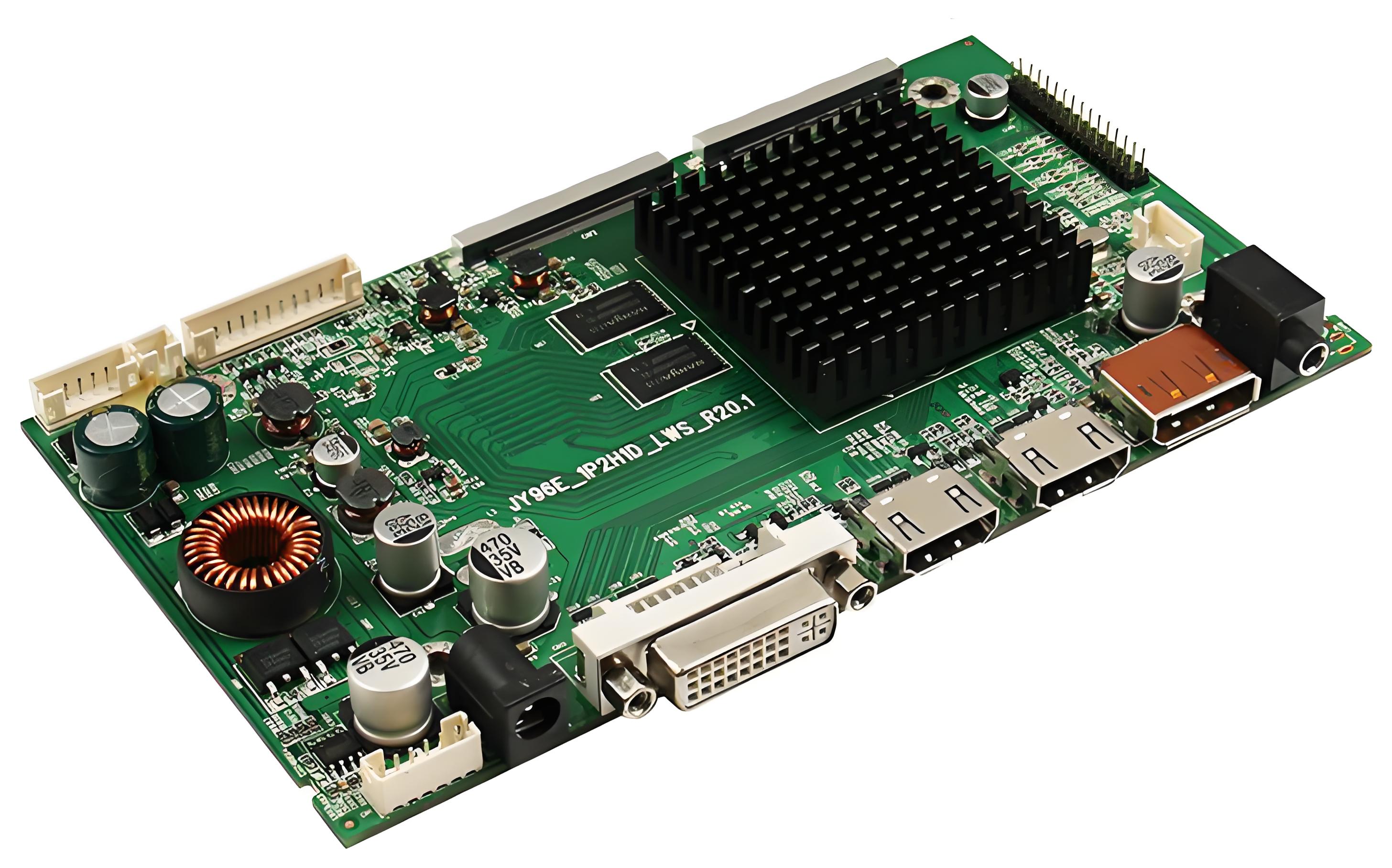
• Component selection and matching: The driver/timing chip needs to be compatible with the screen resolution (for example, high-bandwidth chips should be selected for 4K screens); High-power components (backlight MOSFETs) should be kept directly beneath the screen to prevent heat from being conducted to the panel.
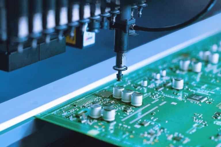
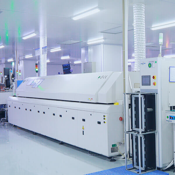
• Placement accuracy control: The placement deviation of BGA packaged chips (such as T-Con IC) is ≤±0.05mm, and the reflow soldering temperature is adapted to the chip specification (peak 235-245℃); After the small components such as 0201 are mounted, check for offset to prevent short circuits.
Fourth. Environmental Adaptation: Enhance durability
• Heat dissipation is not neglected: High-power components (power MOSFETs, driver chips) are closely attached to the heat sink and coated with 0.1-0.2mm thermal grease. A heat dissipation gap of ≥5mm is reserved between the PCBA and the screen body and the casing. For ultra-thin models, a graphite film is attached to provide a wide heat conduction bandwidth for heat dissipation.
• Anti-vibration and moisture-proof protection: For components (inductors, large capacitors) weighing more than 0.5g, apply epoxy adhesive at the bottom for fixation. For damp scenarios (such as bathroom screens), the PCBA should be coated with conformal paint (20-30μm thick), and the interfaces should be covered with waterproof rubber sleeves.
• Reasonable mechanical fixation: The PCBA fixing screws are evenly distributed (one for every 50mm), with a tightening torque of 0.8-1.2N·m, preventing the board from deforming or loosening due to vibration.
Fifth. Inspection and Compliance: Avoid Rework later
• Full function check: Before power-on, measure insulation resistance (≥100MΩ in high and low voltage areas) and withstand voltage (AC 1500V for 1 minute without breakdown). After power-on, test the display effect (resolution, color uniformity) and backlight stability. Run continuously for 4 hours to observe if the screen goes black or if it restarts.
• Compliance matching certification: Key components (power chips, safety regulations components) must be on the certification list of the target market (such as domestic 3C, EU CE) to avoid certification failure
.