
The warping of large-sized PCBs (typically referring to those ≥ 500mm × 500mm) is a common problem in the industry.
The core reasons are the imbalance of internal stresses in the board and the accumulation of thermal/mechanical stresses during the manufacturing process. The following are specific solutions from four dimensions: material selection, design optimization, process control, and post-processing. These solutions cover the entire process from design to production and can be directly implemented:👇
I. Material selection: Reduce warping risk from the very beginning (the most fundamental and crucial step)
Large-sized PCBs have extremely high requirements for the rigidity, heat resistance and dimensional stability of the substrate. The selection focuses on the following indicators:
1、The preferred type of sheet material should be those with high Tg and high CTE stability.
◦ Ordinary FR-4 (with Tg ranging from 130 to 150℃): Suitable for small-sized PCBs. For larger sizes, it is recommended to upgrade to high Tg FR-4 (with Tg ≥ 170℃) or non-halogenated high Tg boards, which have better heat resistance and less stress release after high-temperature processing.
◦ High-frequency/high-reliability scenarios: Optional PPO (polyphenylene oxide), PI (polyimide), or metal-based copper-clad boards (such as aluminum-based or copper-based), offering greater rigidity and superior dimensional stability compared to FR-4, but with higher costs.
2. Matching principle between the substrate and the semi-cured sheet (PP)
(1)Large-sized PCBs are mostly multi-layer boards. The resin content, flowability and coefficient of thermal expansion (CTE) of the core board and the PP must be matched to avoid internal stress caused by the difference in shrinkage rate during the lamination process.
(2)It is preferable to select core boards and PP of the same brand and the same series. Suppliers usually provide matching solutions.
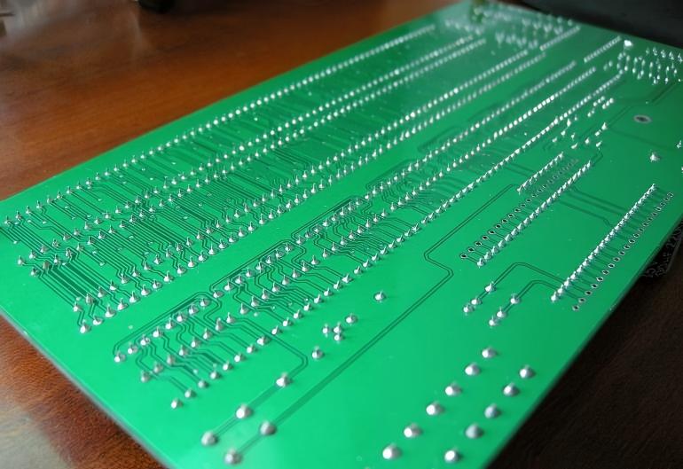
3. Copper Thickness and Plate Thickness Design
(1)The thicker the copper layer, the stronger the PCB's rigidity will be, but it will also increase thermal stress (the CTE of copper is much greater than that of resin). For large-sized PCBs, it is recommended:
(2)Outer copper thickness: 1 to 2 oz (35 to 70 μm) is recommended. Avoid exceeding 3 oz (105 μm).
(3) Total thickness of the board: Adjusted according to size. For PCBs with a size of ≥500mm, the recommended total thickness is ≥1.6mm to enhance the rigidity of the board; for extremely large sizes (≥800mm), 2.0~2.4mm can be considered.
II. Design Optimization: Reducing Structural Stress Concentration
Unreasonable design can lead to uneven force distribution on the PCB, intensifying warping. For large-sized PCB designs, special attention should be paid:
1、Symmetrical design principle (core! Required for multi-layer boards)
(1)The distribution of copper layers, copper thickness, and the number of semi-cured films on the multilayer board must be symmetrical. For example, the copper thickness on the outer layer should be consistent, the thickness of the core board should be symmetrical, and the number of PP layers should also be symmetrical.
(2)Avoid laying a large area of copper on only one side (for example, laying thick copper on the top layer while leaving no copper on the bottom layer), as this will result in excessive contraction force on one side, causing warping.
2. Copper Skin and Grid Design
(1)For large copper-covered areas (such as power layers and ground layers), grid copper (with grid dimensions of 5 to 10 mm) is used instead of solid copper to reduce the shrinkage difference between the copper layer and the resin, thereby releasing stress.
(2)The "window" shape of the grid copper should be circular or rhombic, avoiding sharp corners to reduce stress concentration.
3. Panel and Frame Design
(1)When assembling large-sized PCB panels, add a reinforcing frame (with a width of ≥ 5mm). Inside the frame, set up process edges, positioning holes and support points to enhance the overall rigidity, making it convenient for handling and fixation during the production process.
(2)The connecting bridges between the panels are designed in a plum blossom shape or in a segmented form to prevent the V-CUT from being too deep (the depth of the V-CUT should not exceed half of the panel thickness), thus avoiding the PCB from warping after the separation.
4. Hole Position and Slot Design
(1)Avoid creating large irregular-shaped slots or long-shaped holes at the edges or in the center of the PCB, as this will damage the structural integrity of the board and reduce its rigidity.
(2) If slots need to be made, the edges of the slots should be rounded (with a radius of R ≥ 0.5mm), and additional reinforcing holes or reinforcing copper sheets should be added at both ends of the slots.
III. Process Control: Stress Control during Production (The most feasible and effective measure)
Most cases of large-sized PCB warping occur during high-temperature processes such as lamination, electroplating, and baking. Key control points for these processes should be focused on:
1、Compression process (the main cause of warping in multi-layer boards)
(1)Heating/cooling rate: Slow heating (5-10℃/min) and slow cooling (3-5℃/min), to prevent rapid resin curing or contraction that may cause internal stress.
(2)Pressure control: Implement staged pressure application. The initial pressure (during the resin flow stage) should not be too high to prevent excessive resin loss; during the curing stage, the pressure should remain stable to ensure a tight bond between layers.
(3)Bonding pad: Use high-strength, heat-resistant stainless steel pads, and place a buffer material (such as heat-resistant silicone pads) between the pad and the PCB to ensure uniform pressure distribution and prevent localized stress.
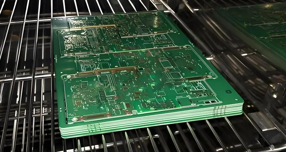
(4)Post-curing treatment: After pressing, a second baking process is carried out (Post Cure), with a temperature range of 150 to 170℃ and a duration of 2 to 4 hours. This is to fully release the internal stress of the board, and it is an essential procedure for large-sized PCBs.
2. Electroplating Process
(1)When electroplating large-sized PCBs, a vertical electroplating line is used to ensure uniform current distribution and prevent excessive copper layer deposition on one side.
(2)After electroplating, a heat treatment process is carried out at a temperature of 120 to 150℃ for 1 to 2 hours to relieve the stress in the copper layer and reduce warping caused by the contraction of the copper layer.
3. Soldering prevention and screen printing processes
(1)Select solder resist ink of the type with low shrinkage rate and high adhesion. During printing, ensure uniform thickness (wet film thickness of 15 to 25 μm), and avoid excessive thickness on one side of the solder resist.
(2)During the curing process, both sides are cured simultaneously or alternately to prevent uneven heating on a single side. For example: first cure the top layer (with 50% cure degree), then cure the bottom layer, and finally complete the overall curing.
4. Cutting and Forming Process
(1)For large-sized PCB cutting, CNC edge routing (Routing) is preferred over V-CUT. During the cutting process, the speed is slow and the cutting tools are sharp, thereby reducing mechanical stress.
(2)After the cutting process, perform stress-relieving baking at a temperature of 100 to 120 degrees Celsius for 1 hour to release the mechanical stress generated during the cutting.
IV. Post-processing and Storage: Preventing Product Warping
1、Deformation correction
(1)For finished PCBs with minor warping (warping degree ≤ 0.5%), thermal pressing can be used for correction: Place the PCB between two flat steel plates, heat it to 120~150℃, apply uniform pressure (0.5~1 MPa), maintain the temperature and pressure for 30~60 minutes, then cool it down and remove it.
(2) PCB with severe warping (>1%) should be scrapped. After correction, it is prone to hidden defects such as inter-layer separation and copper foil cracking.
2. Storage and Transportation
(1)The large-sized PCB products are placed horizontally. They are placed on anti-static hard trays. Anti-static foam is placed between each layer to prevent static electricity. The stacking height should not exceed 5 layers to avoid excessive pressure.
(2)The storage environment should be kept at a constant temperature and humidity (20-25℃, 40%-60%). Avoid direct sunlight, high humidity, or drastic temperature changes, and prevent the board from absorbing moisture or releasing secondary stress.
V. Criteria for Judging Large-Sized PCB Warpage (Refer to IPC-6012)
• Ordinary PCB: Warpage ≤ 0.75%
Surface Mount (SMT) PCB: Warpage ≤ 0.5%
• Large-sized (≥ 500mm) high-precision PCB: Warpage ≤ 0.3%
VI. Key Considerations
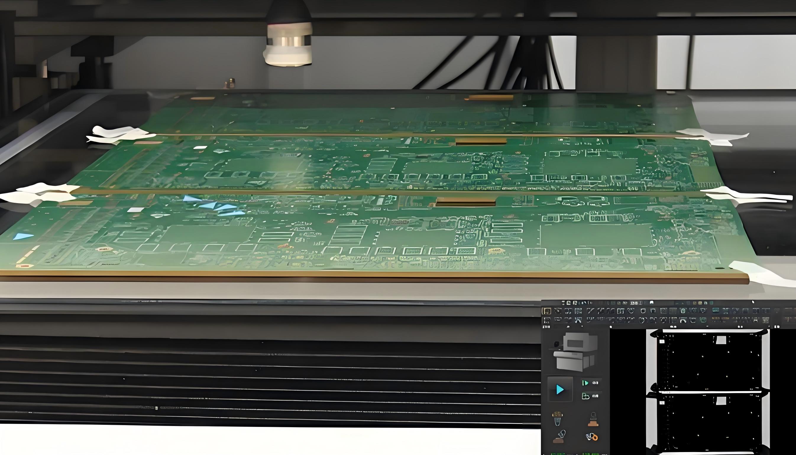
1.During the production process, a record of warpage detection is established. The warpage is measured after each process, and any problems are identified promptly and the process parameters are adjusted.
2. For extremely large PCBs (≥ 1000mm), it is advisable to consider using metal supports or reinforcing ribs. Adding metal components at the edges or central areas of the PCB can enhance its rigidity and prevent warping structurally.
Through the above complete process control, the warpage of large-sized PCBs can be reduced by more than 80%. The key lies in material matching, symmetrical design, slow processing, and sufficient stress release.