

When applying conformal coating, many hardware engineers assume that simply spraying the entire PCB is sufficient. However, this is not the case. While conformal coating enhances a PCB’s resistance to moisture, salt spray, dust, and corrosive environments, it essentially forms an insulating protective film. The issue lies precisely here: some components require this film, while others are adversely affected by it. If the following components are not properly masked before coating, you may encounter unexpected product failures despite having applied the coating.
1.Buttons and Potentiometers
Connectors are typically a primary area to avoid during conformal coating, as their contacts require reliable electrical connection. For instance, if a connector’s contact resistance is originally only a few tens of milliohms, conformal coating entering the contact area effectively adds an insulating layer.
More problematically, while the first mating cycle might scrape off the coating, this does not guarantee reliability. After prolonged vibration and thermal-humidity cycling, the coating may lead to re-oxidation, contamination, or unstable contact. Therefore, the pins, sockets, contact areas, and mating surfaces of connectors usually require masking. Especially in automotive electronics and industrial control equipment subjected to continuous vibration, never assume that electrical continuity equates to reliable connection.
2. Buttons and Potentiometers
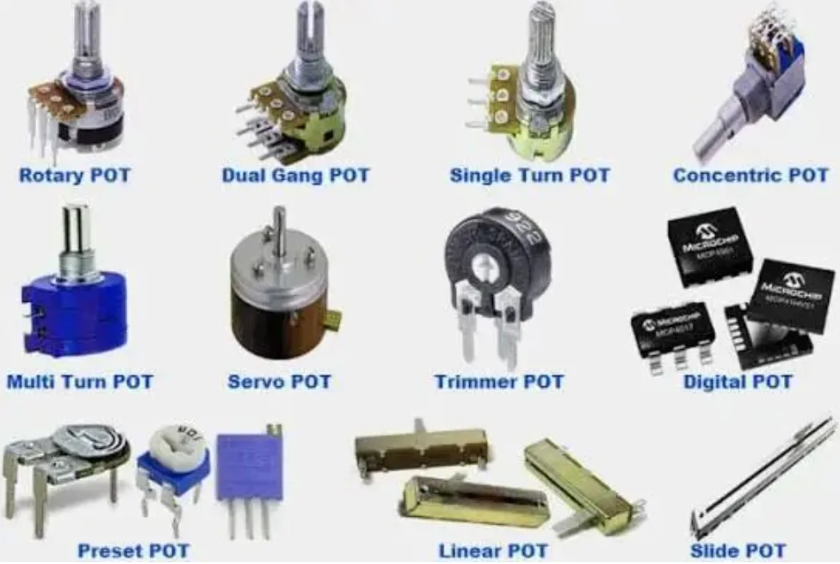
Any moving mechanical parts, such as mechanical switches, potentiometers, and DIP switches, require special attention. For example, potentiometers contain sliding contacts; if conformal coating seeps inside, it acts as a thin insulating contaminant layer on the sliding contacts.
What could happen? Resistance fluctuations, poor contact, and increased noise. This is particularly troublesome in analog circuits, as the issue may not manifest as a direct failure but rather as increased output noise or ADC reading drift.
3. Heat Sinks and Power Devices
Power devices like MOSFETs, DC-DC converters, and LDOs are often surrounded by large copper pours specifically designed for heat dissipation. Since the thermal conductivity of conformal coating is typically much lower than that of copper and metals, applying a coat cannot be assumed to have no impact on thermal performance.
Consider a thermal resistance perspective: if a power device has a power dissipation of P = 2W and the equivalent thermal resistance from PCB to ambient is θJA = 30°C/W, the temperature rise is approximately:
ΔT = P × θJA = 2 × 30 = 60°C
If factors like conformal coating, structural components, and airflow cause the actual thermal resistance to increase to 40°C/W:
ΔT = 2 × 40 = 80°C
With the same 2W dissipation, the device’s junction temperature instantly increases by 20°C. Therefore, for high-power MOSFETs, power inductors, rectifier diodes, and DC-DC chips, the real focus should be on whether the overall thermal path degrades after coating. Avoid covering everything indiscriminately, especially exposed thermal pads, thermal vias, and bare heat-dissipating surfaces.
Strategic Approach to Conformal Coating
I believe the most common mistake in conformal coating is treating it as "the more complete, the better." A more rational approach is to protect what needs protection and leave bare what needs to be bare. During the PCB design phase, coating areas should be clearly defined, dividing the PCB into three categories:
1.Must-Coat Areas: Exposed copper, solder joints, standard resistors/capacitors, and areas prone to moisture and corrosion.
2.No-Coat Areas: Connector contacts, moving parts of buttons/potentiometers, test points, and optical windows.
3.Component-Specific Areas: Power devices, relays, transformers, sensors, and crystals require decisions based on specific component specifications rather than a one-size-fits-all approach.